
Red for the X axis, green for the Y axis and blue for the Z axis. Like many other software with 3D environments, Dynamo uses the known order of basic colors to help to differentiate the axes of the coordinate systems.
In my previous post “Intersecting rails”, it was implicit the potential of Dynamo to automatically replicate and reposition profiles. This is a previous step when making multiple elements at once via sweep or loft. This post goes into the details about how to achieve this and some practical related issues.
Copy + align + ……. = Transform
Geometry.Transform is one of the core methods of Dynamo. It replicates any geometry from one coordinate system to another. The initial and the resulting geometry maintain the same position relative to their coordinate systems.
One habitual use of transform is combined with the methods that return coordinate systems (C.S.) aligned with curves and surfaces. It allows copying directly any geometry following curves or surfaces. In the case of making sweeps, CoordinateSystem.AtParameter (or AtDistance) gives us the C.S. aligned with the paths.

The default axis configuration maybe is not going to match directly what we need. In the sample above the profile is done in the plane XY. So we need the new X and Y axis to be perpendicular to the path. But the default C.S. aligned with the curve are having the Y axis in the tangent direction. The solution is simple, because we can query the axis of the first C.S. obtained to make new ones with the correct axis configuration.
Managing the orientation
Dynamo provides several vectorial tools for controlling the orientation of the profiles. You can read more about them here. The one main is the cross product, which returns the vector perpendicular to the plane defined by two vectors.

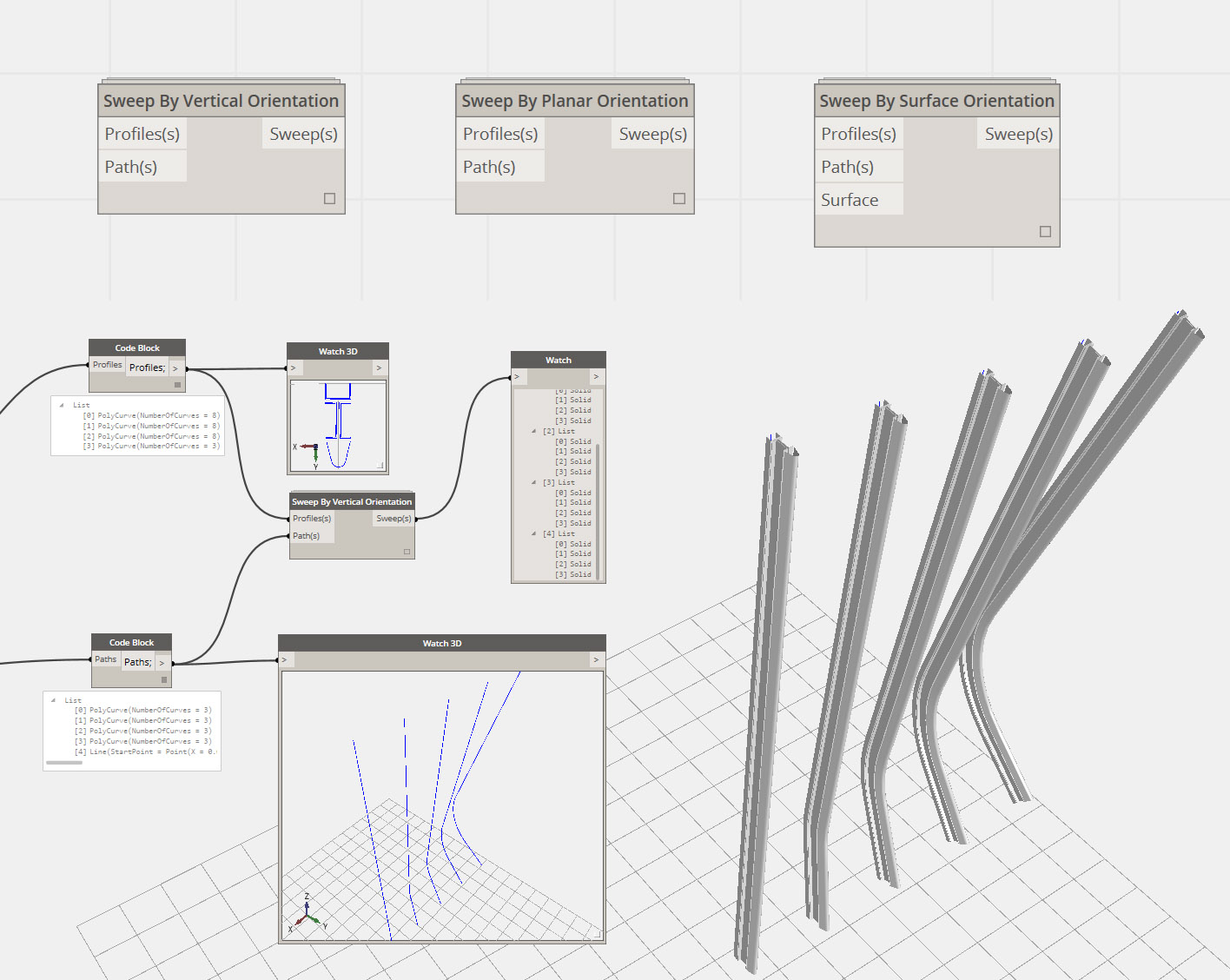
In the sample above I am imposing the vertical orientation of the profiles. That means that if the paths are contained in a vertical plane, the vertical lines of the profile will produce surfaces contained in vertical planes. We can get the correctly orientated X axis from the cross product between the tangent axis and the vertical default Z axis. Having the correct Z and X axis, we can use again cross product for obtaining the correct Y axis.

Another typical situation is when the paths are not in a vertical plane, and you have to align the profile with the plane that contains the path. Making this plane and getting its normal will give us the correct X axis. After this we can follow the same steps as before.
Sweep by orientation
With control of the orientation, we can make sweeps easily. We draw the profile “somewhere” and it will be automatically replicated with the desired orientation. You can find custom nodes with the solutions described above in the package manager.
There is a third typical case, when you use a surface to drive the orientation of the profile. Using the tangent direction at the midpoint of the path and the normal of the surface at that point, we can solve for the orientation in a similar way to the first two cases.
Note that the custom nodes expect the profiles to be drawn in the XY plane using the default origin as reference point. This is important for the workflow described next.
Drawing the profile
In some special cases you will algorithmically define the profile, but normally you will draw the profile in Revit and import the lines into Dynamo. You would probably prefer to avoid drawing the profiles with model lines that are lost in the middle of nowhere in the 3D Revit project environment, and you can manage this with Dynamo in a very convenient way.

Dynamo can take detail lines drawn in drafting views. The lines will be positioned in the default XY plane with Z=0, which means that you can have as many profiles as you want, organized in specific 2D views.
You can see in the image above the custom node “Profile from Revit”. It is a very simple custom node but it can save some clicks. It will extract the geometry of the Revit elements and join curves into a polycurve if more than one segment is selected. It can make several profiles at once.
For consistency and simplicity I always maintain the ref point of the profiles at (0,0). To find the origin in a drafting view you can use the old trick of importing a 2d dwg with something in the origin that you can snap to, selecting “Auto-Origin to Origin” for positioning.
End side cuts
When making elements via sweep, the side ends don’t always automatically match the desired condition of the other elements. In the sample below, the starting tangent direction of the paths tilts strongly at the beginning of the elements.

In this case, I want to finish with a horizontal cut, with different levels for every sub element. We can deal with this quite easily because we can algorithmically define typical boolean solid operations. The first step is to extend enough the paths before sweeping. And later, to make the cut via difference or intersection. The key is that we can directly group the parts with the same cut.

A simple way to make the auxiliary volumes is drawing the rectangles with detail lines in a section view and let Dynamo to create the solid geometry. These lines, when imported in Dynamo, will be in the spatial position of the plane of the section. Again we can draw all the auxiliary lines we need in Revit without “polluting” the Revit 3D environment of the project.

Each sub element is cut one by one, becoming an individual solid after the process. This allows us to regroup them element-wise afterward. In the sample it’s only a few elements, but having even hundreds or thousands won’t make any difference.
Crossing elements
The real power of algorithmically defined boolean operations between elements is to “clean” the joins between crossing elements, especially when they follow complex surfaces with varying angles of connection.

In the sample, the groups of horizontal mullions follow a nonlinear distribution controlled by splines drawn in Revit. As “usual,” I am using a drafting view for this. Later I am making an auxiliary surface from every group that will drive the orientation of these elements. The axes of the mullions are defined between the borders of the outer part of the main elements. The initial mullion elements following the geometrical axis do not have a clear end in the main elements.

The solution is similar to what we saw previously. We first extend the axes of the elements, then cut them with aux. volumes, this time via sweep using the path of the main elements. For the big cover of the mullion, a gap in angle is needed.
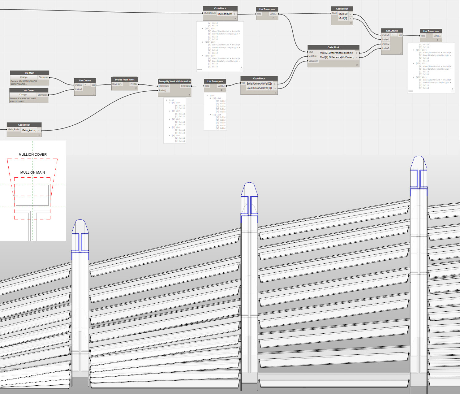
I don’t need to group mullions related to their specific side main elements. Instead, I can join all the aux. volumes in one solid that will be used in one global solid difference operation. This simple operation “cleans” the joins, one by one, of the 140 mullions. As before, every subpart of every mullion remains an individual element.
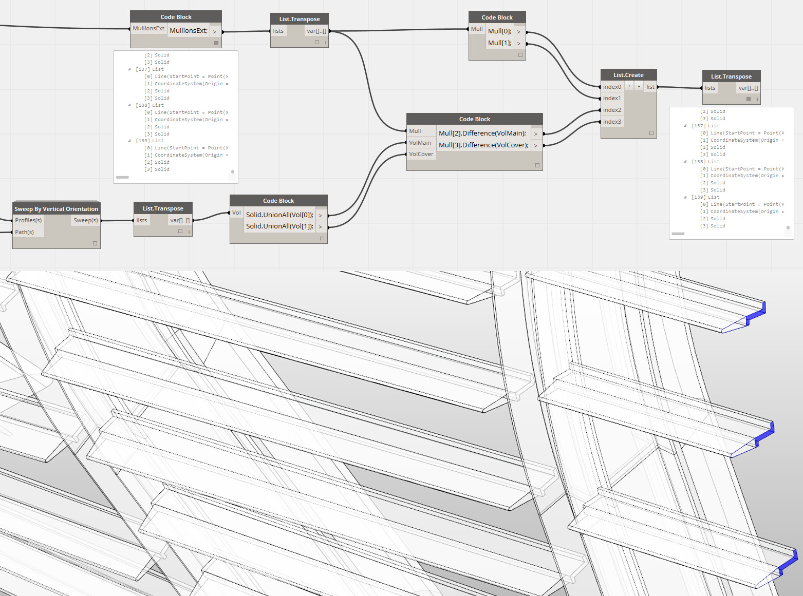
The list of data for each element is not just the main part and the cover. The geometrical axis (before extending) and the related coordinate system is also included. The axis gives the geometric reference of the mullion at any moment. The coordinate system enables us to easily get parallel views to the element, allowing for possible workflows for automatically creating shop drawings.
A different Revit
From the very beginning of Revit, we have defined 2D profiles that will automatically be placed for generating solid geometry, for example with detail profiles families for curtain walls mullions. But doing the same with total freedom for any kind of geometry, with precise control of the spatial position and joins between the elements, is quite a different situation.
It has only been a few months since the first release of Dynamo with the new geometry tools. We have to try to develop new possible workflows. And we really need more built-in methods for transferring the geometry created in Dynamo to Revit. But we already have the tools for direct and transparent control of complex geometries.
If you are developing non-conventional buildings in the later project stages, you need the flexibility to deal with unusual geometries as much as the accurate control of the geometrical positions and connections between elements. For this, Dynamo converts Revit into a radically different tool.