Unfolding Planar-Faced Models
For the last few months I have been working on an intern project at Autodesk for the Dynamo team on the unfolding of planar-faced Breps, solids, and sets of surfaces. Initially, I started working in Dynamo and Python but decided to switch to C# and zero touch import.
Zero touch is a way to create reusable nodes in Dynamo from C# code with minimal Dynamo-only code. I have found this way of working, using C# and Dynamo to visually debug, pretty awesome. I’d like to share what I’ve been up to, get feedback from the Dynamo community, introduce zero touch library importing, and my experience working with it. All the code for this work is hosted on github in the DynamoUnfold – if you want to play with this code you’ll need to build Dynamo, DynamoText, DynamoPack, and DynamoUnfold from source.
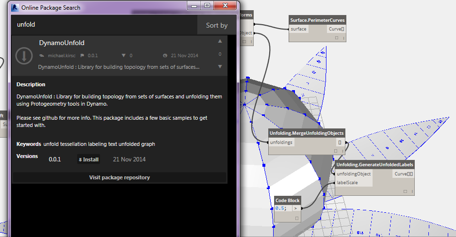
OR: just get it on the package manager!
*If for some reason you just want to use this library, but don’t want to use the package manager, you shouldn’t have to worry about building it, check the Pre-Built folder in the github repository and import DynamoUnfold.dll into Dynamo using the import library menu option.
Note : The code is still in a bit of flux. There are a few bugs that crop up with unfolding large models I’m still hunting down.
I welcome forks of this code, discussion, and contributions from others. There are a bunch of places where I know the code is inefficient (converting triangles to surfaces!!, mass intersection of surfaces a polynomial number of times, joining of surfaces into polysurfaces… ), and there are still some really interesting fundamental problems to solve.
State of the Code, an aside
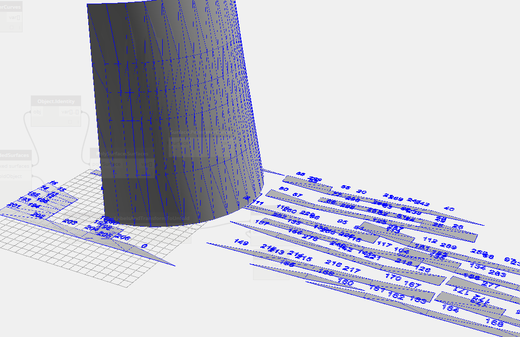
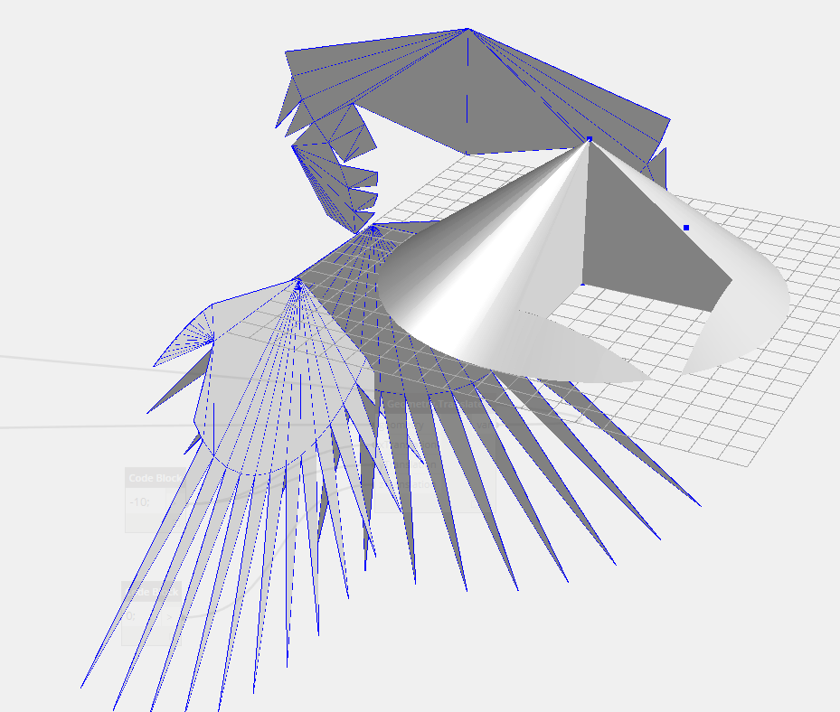
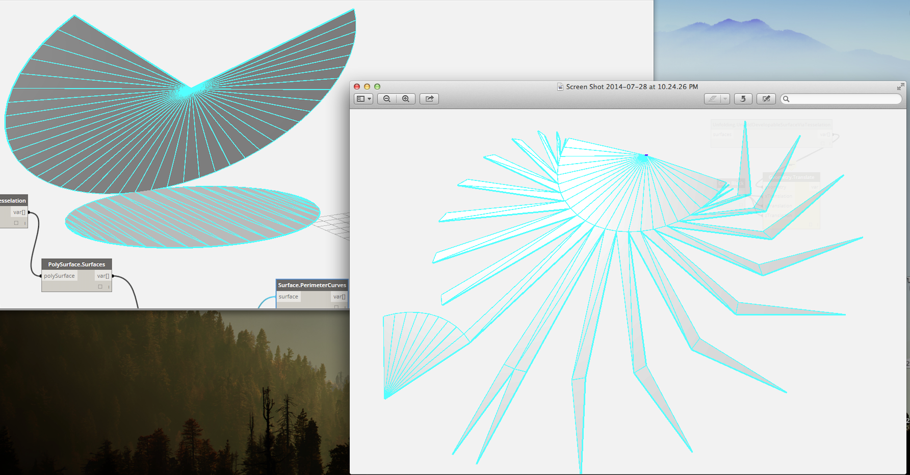
As built at the moment of this writing, this library will attempt to unfold a set of faces, set of surfaces, or a set of surfaces that it will explicitly triangulate, and then unfold the triangular representation. It will not attempt to recognize true developable surfaces like the cone (more below). Instead, to unfold a cone or any curved surface, you must pass the surface geometry of the cone explicitly to UnfoldCurvedSurfacesByTessellation() or Use TessellateSurfaces() to tessellate the surface into a series of triangular surfaces and then pass these to the other surface unfold methods. You can of course rationalize the surface as you see fit into a set of sub surfaces and pass those to be unfolded, more later.
What This Library Can Do
This library gives you a set of nodes to unfold sets of Faces, Surfaces, or triangulated Surfaces. Faces might come from a solid geometry, surfaces might come from an extrusion or loft. The three examples below all take some surface geometry as input, tessellate it, and then unfold the resulting tessellation.
There are also nodes for generating labels, before and after the unfold. The labels are just curve geometry, so they can be generated in Dynamo standalone.
Last, there is a node to pack the resulting unfold parts into a bounding box of the required size.
Some Small Samples
*Note that the structure of this library will probably be changing a bit so that it’s more useable and intuitive. Some repetitive nodes will be removed and some workflows will be made simpler. It would be great to get feedback on workflows that users want, but this library does not yet support or are not easy to implement.
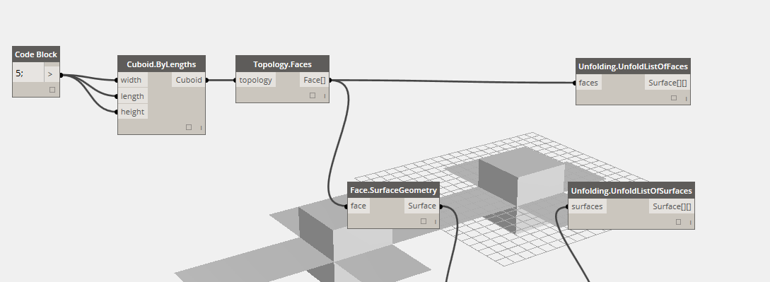
1 .The repo includes a samples folder. The first sample, CubeUnfold, unfolds a cube by surface geometry and faces. The faces are extracted from a solid, and the surfaces are extracted from the faces. Note that there are different nodes for unfolding lists of faces and surfaces.
2. The second sample, CurvedSurfaceTessellateUnfold, shows a more complex unfolding operation.
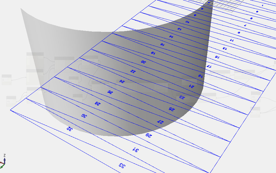
In this sample, we have some curved surface that we tessellate to some level of precision. The resulting list of surfaces is passed to the unfolding nodes. We use the UnfoldListOfSurface_AndReturnTransforms node to unfold the list of triangles, and also return the UnfoldingObject – this is a representation of a single unfolding operation, which was performed on a list of surfaces or faces. The unfolding tracks each surface through the unfold and lets us map things to the final location, like a label. This means that currently, if you unfold multiple lists of surfaces then each of those lists will generate separate unfolding operations, and the IDs will apply only to that unfolding. This will come up in the third sample.
After returning the surfaces and unfolding we use the GenerateInitialLabels node to generate some integer IDs and place them on the original surfaces. Then the GenerateUnfoldedLabels node does what you would expect and places labels with the same ID at the unfolded location.
You can see that the PackUnfoldedSurfaces node requires only the UnfoldingObject as an input, not raw surfaces. This is because the UnfoldingObject stores the surfaces and the transforms through the unfold. This node returns the packed surfaces as well as a new unfolding that lets us label the packed surfaces.
You can see that all label and packing nodes require an unfoldingObject, not raw geometry because we need to keep track of the transformations performed on the surfaces.
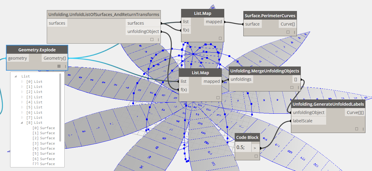
3. The third sample, SphereUnfold, shows a pre-rationalized manual unfolding operation and introduces MergeUnfoldingOperations().
In this sample, the UnfoldListOfSurfaces_AndReturnTransforms node is mapped over a list of nested lists of surfaces. List<List<Surface>>. This mapping returns 9 different UnfoldingObjects, each of which represents an unfolding operation and a list of the associated unfolded surfaces from the surfaces output.
To pack or label these separate unfolding operations all together, we need to merge() them together into one unfolding. This will update all the surface IDs so there are no overlapping IDs, and store all the transformations in one large map. The MergeUnfoldingOperations() node accepts as input a list of UnfoldingObjects, which is exactly what the second map node returns in the sample. The final output is one unfolding operation that can be packed or labeled as usual.
This workflow gives you the most flexibility to divide up the unfolding operations into separate jobs you can control and then merge them all back together for labeling and packing.
Why Unfolding and Unrolling?
Image Credit: Walt Disney Concert Hall Logo” by Justefrain – Own work. Licensed under CC BY-SA 3.0 via Wikimedia Commons.
Unfolding and unrolling polyhedra and developable surfaces are related problems. The code discussed in this post deals only with planar faced polyhedra and other solids. To unroll a developable surface with this code we can approximate it by a series of planar faces.
Developable surfaces are a subset of surfaces that can be defined by a series straight ruling lines, along these lines the normal direction at the start and end points are parallel with each other. They have many uses in the context of fabrication because of their properties of constructability.
They can most eaisly be modeled by taking a sheet of paper and twisting it or bending it, without crumpling the paper, all shapes that you are able to make will be defined by a series of straight ruling lines, it stems from the fact that the paper cannot stretch.
Gehry Partners and others make use of the properties of developable surfaces to construct curved surfaces, where in reality, the structural members are straight ruling lines.
The ability to unfold or unroll models is useful for fabrication, model making, and documentation. One can imagine unrolling a complex facade elevation to document it, or even use the unfold as part of the design process, drawing directly onto the unfolded surface, and refolding to see the resulting pattern applied. Once you have an unfolding it’s possible to lasercut, cnc, or handcut the unfolding and put together a model quickly, even for complex shapes. At this point, the code doesn’t handle things like tab generation, but I’ll describe the idea later. The other thing to note is that some unfoldings (even for the same models) will be much easier to construct than others, so we may want to think about metrics for a good unfolding.
Background
Unfolding is a well studied area with lots of interesting open questions. Professor Erik Demaine’s website on folding at: erikdemaine.org has some excellent links to papers, discussions, and code for unfolding.
Approach
One approach to the unfolding problem is to consider the topology of the object to be unfolded as a graph. In this graph each vertex represents a face in the object, and each edge in the graph represents a coincident edge shared by some number of faces. This graph lets us travel from one face in the object to all adjacent faces, and to reason about these adjacencies. We can build this topology graph by looking at all faces of the model and each edge of that face, if we see an edge twice than we have found a shared edge!
Also graphs are cool.

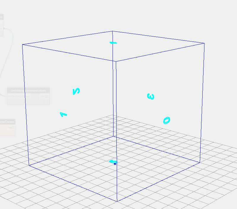
-This is the graph that represents a cube, every face is connected to four other faces
In general if we traverse this graph and find a spanning tree, we have found one possible unfolding for the object.
- A tree is a special kind of graph where there are no cycles, and no vertices that are unreachable.
- A cycle is a loop.
- A spanning tree is a tree that includes every vertex from a graph.
So after all that jargon, what we are looking for is a subset of the graph that includes every face but only some edges. These remaining edges are the edges we fold around.
The tree represents not the topology of the object, but the faces, and the edges we will fold them about to produce the unfolding. So finding some spanning tree is the big step that will let us find a possible unfolding.

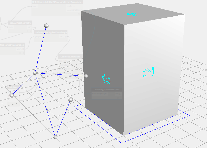
– One possible spanning tree of our cube

– Another possible spanning tree of a cuboid, this one represents the faces as tessellated triangles so we have 12 faces instead of 6
A spanning tree is not difficult to find for some graph, but the trick is that there are many many many possible spanning trees for most graphs. Most of these will produce different unfoldings. How do we pick which one to actually unfold? A good question. Many of these unfoldings will produce unfolds where the resulting surfaces are overlapping each other. This is not very useful if our purpose is to take the resulting surfaces and cut them out for fabrication. I’ll revisit this question later in this post with some possible solutions.
Algorithm
Once an unfolding tree is found, one can rotate the leaves of the trees to be coplanar with their parents, merging those coplanar faces together and doing this iteratively until all the faces in the tree are coplanar. The leaves of the tree are just the faces in the tree that have no children of their own. The unfolding algorithm is this simple process. The rotation is done two graph vertices at a time, and as the faces become merged together we rotate those merged faces as if they were one. At each step we must calculate the angle between two surfaces, the child and its parent.

Explicity The steps are:
- find a leaf in the tree – this is a face we’ll fold, that has no folds after it, call this the child
- find this face’s parent – the parent represents the face we need to make the child coplanar with.
- find the edge that points from the parent face to the child, this edge represents the edge we’ll rotated around, the fold edge.
- rotate the child to be coplanar with the parent.
- check if this rotation caused any overlaps to occur with previously unfolded faces.
- if not, then join the parent and child surface into a polysurface and store this polysurface in the tree node that used to represent the parent face.
- remove the child node from the tree – this is a contraction of the parent and child nodes into one node.
- repeat until there is only one node left in the tree.
This process outlined above is almost the entire story. There’s a bit more that happens if there is an overlap.
Dealing with Overlaps During The Unfold
If during the algorithm outlined above, the rotation of the current surface to be coplanar with its parent, causes an overlap of a previously unfolded face with the current face, we need to do something. A simple solution is to move the current surface away from the rest of the unfold. It’s either a single surface or some chain of already coplanar surfaces, so it’s safe to stop unfolding it and put it somewhere else. We can make it planar with the rest of the unfolding at the very end. Problem solved …Well…Kinda…
What’s the worst case? That every time we rotate a face up to be coplanar with its parent we end up with an overlap, then we wont have a nice unfolding, but just a bunch of separate faces, still useful, but not great.
As I mentioned before, this hypothetical unfolding that is causing all these overlaps is not the only unfolding for this hypothetical model. There exists many more unfoldings we could try. At this time, this idea is unimplemented, but one could think of this problem as an optimization or search problem, minimizing or searching for a small number of subparts for the unfold. You would need some way to generate a random unfolding tree, a way to modify that unfolding tree, and a way to evaluate the final unfolding.
This should lead you ask the question, what if there is no good unfolding for a particular model? Well that is one of those interesting open questions surrounding the study of unfoldings. Does there exist a simple (non-overlapping) unfolding for every polytope? So, since that’s an open question, we need some way of stopping this search if we can’t find one fast enough. Iterating all possible spanning trees could take… a while. It’s difficult to define the number of spanning trees in terms of verts and edegs of a graph, but it is almost certainly too many to brute force through in the time we would like in Dynamo.
Simple Implementation
To find some spanning tree I’m currently using an implementation of Breadth First Search. It’s fast and simple. It gives us two nice attributes when it’s finished. A tree, and a distance associated with each node in the tree. This lets us quickly find the leaves of tree, since the highest distances will be the leaves, so we can sort the tree by the distance of each node. Keep in mind BFS only produces one possible unfolding, and it could be one with many overlaps, even if a simple unfolding exists.
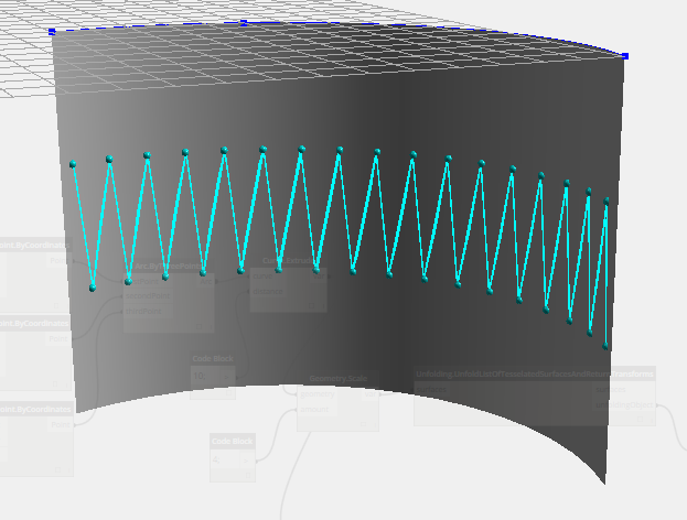
– The spanning tree generated from this developable surface represented as a series of triangles – the spheres represent each face, the edges represent the shared edges, but note these are edges in the tree, not geometrical edges!, also this tree is really easy to unfold, it’s a linked list! AND it’s also a Hamiltonian Path – it’s guaranteed to have a simple unfolding
So Many Surfaces! – Dynamo’s Geometry Library
Interacting with Protogeometry through C#, Dynamo’s wrapper for Autodesk Shape Manager is fairly simple in most cases. The methods are the same ones that are exposed in Dynamo as nodes, so they should be pretty familiar.
Creating Geometry
The first thing to note, is that like the methods exposed in Dynamo, to create new geometry we don’t use the new keyword, we use static constructors in the class of the geometry like in Dynamo or DesignScript.
var myNewPoint = Point.ByCoordinates(0,0,0);
Another important aspect of the library is that these geometrical entities are mostly immutable. When you perform any kind of geometrical transformation you are producing new geometry. This is great, and causes some headaches as well.
var anotherNewerPoint = myNewPoint.Translate(1,0,0);
Some Headaches
The headaches with immutable geometry arise when you want to tag some instance of geometry with some information. For example, we want to tag a specific face in our unfolding with a label. It would be nice to be able to tag this face before running the unfolding algorithm, and when the unfolding is finished, iterate each face and grab the label and display it. We can’t do this, since the final faces of the unfold are all brand new surfaces, and won’t contain any information we tag them with.
The solution that I use in this code is to build a map of transformations to geometry that tracks all the transformations that apply to a set of surfaces. For the label example, we can now iterate the original faces, lookup the label we associated with the original face and then lookup the transformations that apply to this face throughout the unfold. Then just apply all the transformations to that label, and it will move to the final position, as if it had been associated with the face.
Actually moving this information through the unfolding is a bit trickier, but it’s very similar to merging the parent and child surfaces together and storing them in the parent surface. At each step of the unfold we want to record the new coordinate system of the rotated faces, and which faces were actually rotated.
Working With Zero Touch and Protogeometry.
For some issues with running unit tests for zero touch nodes on top of protogeometry check the readme on DynamoUnfold. The short version is that Dynamo uses host applications on your machine to drive its geometry engine, and to test a standalone project that uses the geometry engine, we’ll need to reference some of those applications as well. The state of this interop should become much simpler in the future, for now it’s just a bit of work to get testing. (In fact, that work is being done on the zero touch samples right now by Ian himself.)
I hope you enjoyed this blog post, I plan to continue refining the repository and cleaning up the build process and functionality. Have fun.
