This blog series dives into leveraging Dynamo to orchestrate and unify data and design logic for residential building configurations with Forma and Revit. To understand this connection you can learn more about Dynamo in Forma here. For a deeper dive into why this matters, come take a read of the first blog post in this series.
The challenge in AEC isn’t a lack of powerful tools, but rather the quest for seamless integration—a void addressed by the new Forma-Dynamo synergy. This isn’t just an added link; it’s a pivotal integration set to unify workflows/datasets, connect your firm’s proprietary design logic (your “DNA”) from initial conceptualization in Forma, all driven by the same Dynamo graphs that will later generate detailed Revit models.
Before we Begin Running the Graphs
In this blog post, our goal is Unified Residential Design logic. We’ll configure residential buildings, with the core requirement being to use Dynamo to orchestrate singular data and design logic between Forma and, in a future post, Revit.
If you haven’t yet set up Dynamo Player in Forma, follow these steps to get started: Set up Dynamo Player in Forma.
It’s important to remember that while Dynamo itself is unitless, Forma requires metric inputs. Therefore, our graphs for Forma are in Metric.
Quick Start to running your graphs

Dynamo’s Workflow
Follow these steps and watch the videos below to learn how to configure residential buildings using Dynamo with Forma.
- Download and Extract Zip file into a folder (Link to 2 Dynamo files and 1 excel Document).
- Open Revit Project, Dynamo and provide graph (ResidentialConfigurator-01.dyn)
- Open Forma Project and match Building Function Setting shown in image below. Be mindful to make sure all of your Building Functions are correctly capitalized.

Building Function Settings
- Open Extensions and Dynamo Player Beta and Desktop and open provided graph (ResidentialConfigurator-01.dyn)
- Verify that the excel document is pointing at the correct file
- Run graph and review results
- Change Unit Sizes in Dynamo Player
- Run graph and review results
- Change Floor Count in Dynamo Player
- Run graph and review results
- Change excel document “UnitTypeMix-01.xlsx” both unit types and counts, save and close excel
- Run graph and review results.
- Close Dynamo file and open “ReadFormaGeometryForRevit-01.dyn”
- In forma use the update button, select a level in a building, confirm your selection
- Run graph and review results.
Explaining what happened

Graph break down and descriptions below
#1 : Excel Input that reads Unit Types and Counts
Inputs and distributes = Excel Unit Types sequence and counts throughout graph. Notice, the Excel Unit order is the same order in the building layout. This is a list of the 4 Unit Types that are used in the Excel document for this demo. ONLY use these names in all CAPS: STUDIOA, STUDIOB, BED1A, BED2A
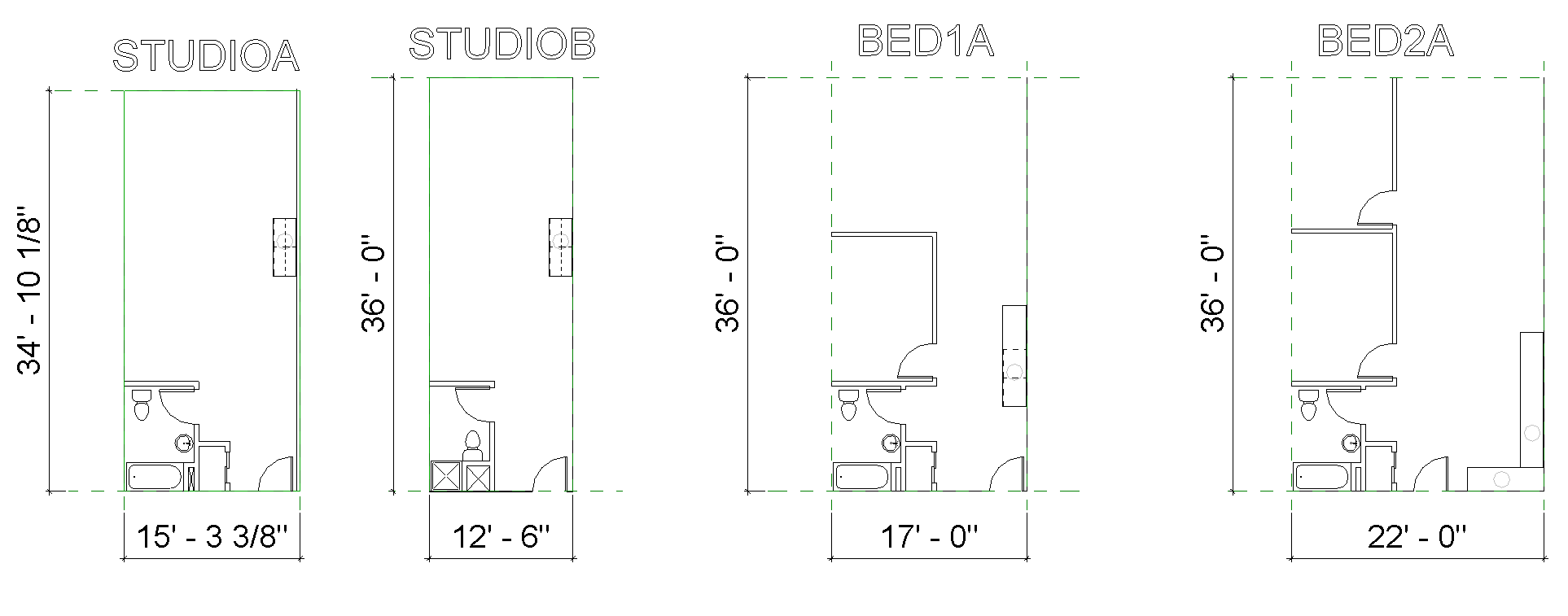
Unit Types (STUDIOA, STUDIOB, BED1A, BED2A)

Excel inputs and order correlates to model output
#2 : Dictionaries for each Unit Type and Dynamo Player inputs
- Inputs and distributes = Unit data throughout the graph.
- Keys = Unit Name, Length (max., min.), Width (max., min.).
- Rules = Guides the user to design within the min. & max. values
The image below demonstrates how a simple Dynamo slider, controlling the size of “StudioA,” can enforce crucial design logic. While this particular rule is straightforward, its significance is profound: it can prevent the generation of designs that don’t meet product specifications, ensuring only shippable configurations are produced. As our tools empower us to create more designs, it is crucial to build trust in our output by embedding design rules (DNA) directly into the process.

Simple slider rule with a tactical use case
#3 : Dynamo Player inputs for Floors, Floor Height and Corridor Length
- Inputs and distributes = Floor and Corridor values throughout the graph
- Rules = Guides the user to design with the min. & max. values
#4 : Combines Dictionary Keys and Values (#2) in a single list, filters out units that are not used (compared to the excel document #1)
- Filters and distributes = all provided unit types, their keys and values
#5 : Recalculates unit value based on “simplified” rules and design logic
- Calculates and distributes = new unit calculations
- Rules = Stacking Units, Unit grouping, Building Left to Right
Here’s a breakdown of the core rules governing our building configurator, ensuring a consistent and predictable outcomes.
- Linear Building Shape (Rectangular):
- Rule: The building always originates at the coordinate (0,0,0) and extends along the X-axis to a specified length.
- Unit Grouping along a Shared Corridor:
- Rule: Each unit grouping will have identical units on both sides of a central corridor. The total length of a unit grouping is calculated as: (2×UnitLength) + CorridorLength.
- Vertical Unit Stacking:
- Rule: Units will stack vertically, maintaining the same unit type in all conditions along that vertical alignment.
- Unit Ordering:
- Rule: Units will be grouped and placed according to the sequence designated in the Excel document (see #1 image).
- This building configurator’s design logic necessitates recalculating the Excel inputs (#1). If you’re curious about the mechanics behind this, refer to the Dynamo graph [ResidentailConfigurator-01] and locate the “GET NEW TOTALS FOR UNITS SO THAT BASE LINE RULES ARE MET” group.

Core rule governing the configurations
#6 : Dynamo Player output of new Unit Count
- Output = to player with recalculated Unit values (from #5)
#7 : Calculates values related to Unit Width
#8 : Calculates values related to Unit Length
#9 : Calculates and organizes PolyCurves
#10 : Forma Nodes
- Output = Model by BasicBuilding.ByCurve, BasicBuilding.ByUnits, BasicBuilding.ByPlans
#11 : Forma Node (NOT CONNECTED) (this is for you to play with, see Dynamo Group for details)
- Output = Model by GFAUnits.ByCurveAndElevation, GFAUnits.ByUnits, Integrate.ByRepresentations
Closing Thoughts & Future Horizons: Connecting Rules and Design Logic to my ecosystem.
Although the logic we have chosen is simple, there are much more complex rule sets. Allowing mass customization at scale but guided by your rules and design logic.
The Secret Sauce: Here are some items that caught my attention. Choosing your authoring node is key as to what kind of output you want to produce. When it came to exploring authoring nodes in Dynamo for Forma, I explored every available option and their outputs, ultimately selecting Node grouping #10. I admit, I could easily spend weeks diving into the nuances of these nodes’ input values and their potential for generating rich data (because they all had value). I truly believe there’s more power here than this post can cover, which is why I’ve named it “2.1.” I’m eager to revisit these inputs and their possibilities in future deep dives to fully showcase their capabilities (there is more here than meets the eye).
With these outputs from Forma, Revit users can directly connect a unit type to its insertion point and sketch data. I’ll demonstrate the significant value of this in blog post 3. This crucial data connection, among others, is what excites me to explore further. Once again, THERE IS SOME REAL POWER HERE! How far can we take it
Homework: before next post
Create Building Configurations by flexing the Excel document, unit sizes, floor counts and floor heights.
Post 3: What’s next
We’ll be exploring the out-of-the-box Forma to Revit geometry workflows, with a particular focus on how the “ReadFormaGeometryForRevit-01.dyn“ graph processes the Forma model‘s output. We’ll then demonstrate how to align and place Revit content precisely with these output points, connecting the geometry from both platforms. I’m excited to show this next connection! I’m excited to see where you/we can take this . The video below showcases Forma pushing geometry through Dynamo’s user-defined rules to dynamically drive a Revit model!. Learn more in Post 3 – Coming soon.