Introduction
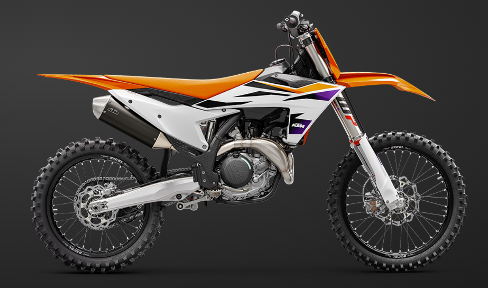
For over 30 years, KISKA has designed the brand and motorcycle portfolio for KTM Sports Motorcycles. Nowadays, this task includes KTM, Husqvarna and GASGAS. A few years ago, a trend started to emerge on the market to generate interest in new products by adding parametric pattern elements on certain areas. This idea generated a controversial internal debate for a while, as the KTM Brand (as well as KISKA as an agency) believes in honest and performance-driven design solutions – and a no-nonsense approach. We didn’t want to add patterns just for the sake of them. There had to be a purpose.
Our design team settled on a simple rule: Patterns are welcome in areas of the bikes where there’s a lot of physical stress involved. Stone impact, crashes from falling to the side when improperly handled, areas which require more grip than others, etc. Patterns will act as protection, and as a tool to hide natural wear-and-tear.
Brand Impact
The three brands of KTM, Husqvarna and GASGAS represent very different values. For example, KTM sports the “READY TO RACE” approach, focusing on performance, purity and the extremes of motorcycling. Husqvarna is more grounded, with a commitment to smart and dynamic products which feature pure design and progressive features. GASGAS is the playful brand; daring, capable, vibrant and inviting everyone to join in.
When developing patterns, this meant the system we created needed to be both flexible and strict. The main challenge I identified was keeping things consistent for the development team while allowing for brand freedom.
It was also clear from the start that traditional modelling techniques had to be reduced to the minimum. In a design environment, changes are the daily ‘bread and butter’. Expect them to come often – and in the worst moment possible.
Why Dynamo?
With the briefing sorted, it was time to move forward and provide a workable parametric answer to the questions asked. I knew about both tools available on the market at this point, Grasshopper and Dynamo. Three things influenced my decision on Dynamo:
- Dynamo comes fully integrated with Autodesk Alias, our main tool for production surfacing.
- A friend of mine, Pierre-Paul Andriani, came to visit us and gave us an intro to Dynamo and how he uses it.
- Dynamo can be extended with ZeroTouch nodes written in C#.
Seeing is believing, and the potential was clear from the start. I’m not saying this was an easy journey for me, nor that I was always confident to reach the target. But slicing the problem helped, and the great support from the Dynamo community kept me going.
Why not Dynamo in Alias?
It sounded like a dream, parametric design directly embedded into your main tool of choice, no interfaces, no data conversion inbetween. However, my own limited skills in Dynamo in the beginning and lack of understanding how the two tools interact with each other led to the worst possible result: Crashes, loss of data, loss of input assignments…Recovering my Dynamo work meant: To restart Alias, open a specific file, and edit the Dynamo history feature to open the connected node tree. It was simply too complicated. Luckily at that time Dynamo Sandbox was already a thing, so I jumped on that train and used the well supported SAT interface to exchange data.
KTM example

Initial sketch input from designer
Starting off with a sketch, I negotiated the elements of the pattern which were supposed to be parametric. Height, length, distance between stars, alignment to neighbours and so on. At the same time, I counter-checked with the current vehicle design. The areas to wrap the elements on were the top part of the spoiler as well as the frame guard. Both are parts that are scratched quickly during usage, by rider boots, leather, stone impact or tree branches hitting the zones.
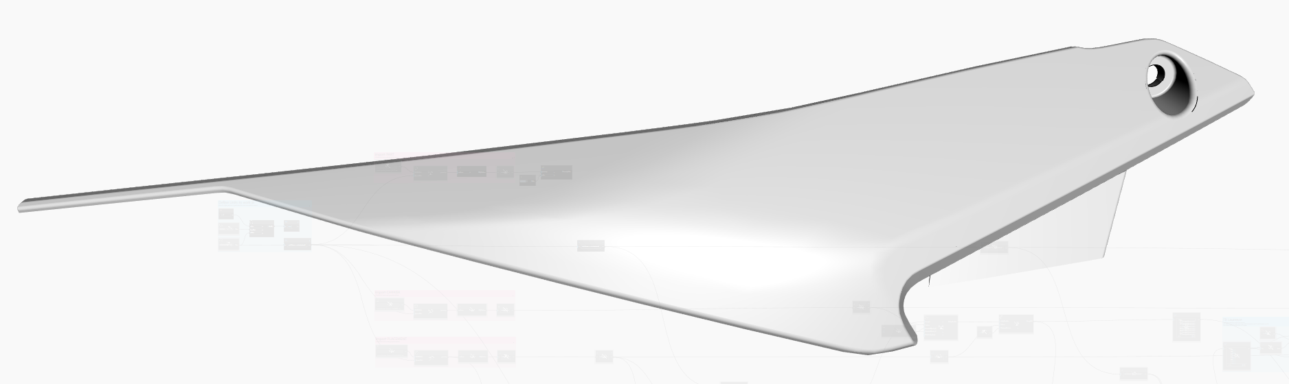
Spoiler part to receive a pattern
There are, of course, areas that should not be wrapped. To define these, I settled on a traditional approch. Provide separate input surfaces for:
- Finding stable element distribution (Carrier).
- Defining where elements shall remain (Placement).
- Trimming elements at borders (Flange).
- The part itself.
Working on many of these patterns, I learned to keep the input especially simple. The design constantly updates. The part itself as well. There might be manufacturing reasons that trigger changes. The less sophisticated the input logic is (a. k. a. finding targets and attractors), the more stable and agnostic it is to update. Dynamo is visual programming. It adheres to the same principles. Keep It Stupidly Simple.

Overlay of Carrier (grey) and Placement (blue)
The beauty of ZeroTouch
The beauty of ZeroTouch libraries is the encapsulation. It makes node trees simpler, perform faster, and allows you to use all the benefits of C# code language, like inheritance, interfaces and so on. I mentioned in the beginning that making things consistent for the end user was a goal for me. Interfaces and inheritance were the answer. See this short snippet here:

Typical header of a pattern node library
This process allowed me to invent a new object type: a pattern element. Using interfaces, I could create a new pattern ensuring I’d at least support a minimum set of nodes for the user that each element offers. Like, FilterByDistance, or PerimeterCurve. Others could be kept flexible. Is this an element that should simply use a ToSolid node? Or do we need something like Extrude instead? That part I kept flexible per pattern.
Another huge benefit is the ability to draw custom previews per node. So, when a user now instantiates a new KTM_SX_Star in a node tree, he would not need to make it a Solid first. A much quicker low-poly preview would guide him until the moment he really needs those Solids in hand.

Stars drawn using custom previews
Finding your way
There are repeating tasks to be performed no matter the pattern. You need to find a starting point. You need to define origin points, tangents and normals for each pattern element. Those need to be stable when the underlying references change. It’s surprisingly difficult to find these references when the underlying geometry is not predictable. We are dealing with trimmed NURBS patches here. So, any approach to finding those placements by using UV nodes are futile. Unfortunately, pretty much every tutorial you can find points you towards such a solution. You’d have to remodel the part with a single surface patch, sporting perfect UV spacing. With most parts I was dealing with, this was simply impossible.
Researching this problem, a co-worker pointed me at the work of Russian math scientist Pafnuti Chebyshev. His work on describing geometry using quads, so-called Chebyshev nets, was the inspiration to a complete ZeroTouch Library I developed for our company.
The principle behind
Starting from a triangle, which touches the target surface (quilt), take a copy of that triangle and roll it along one of its own sides, until the free tip touches the target geometry again. The resulting shape is a quad, the roll axis is its diagonal. Now take another copy of the initial triangle, and move it along one of its sides. You need to place it coincident with the corner of the diagonal, and the new 4th point. Roll this triangle’s tip onto the target surface. You now have created a new diagonal to work with. Then, roll along the new diagonal again, repeating the process.
Repeating this you can expand a strip of quads across an arbitrary surface, where all quads have stable lengths in X and Y. Mind though that the angles can collapse. Google ‘Chebyshev nets’, and you will find illustrations of the results.
The final implementation I found would preview the resulting triangles, their origin point and their normals nicely. The triangle itself is also a custom class, with custom drawing code. The resulting Chebyshev net on the part in this example looks like this:

Chebyshev net spawned across the placement surface
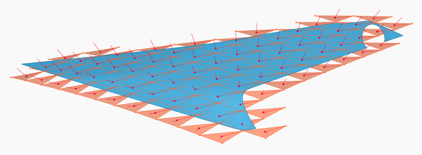
Filtered triangle candidates where pattern elements shall be drawn in
Divide et impera
That simple-looking red or green triangle is the base of every pattern I create. It’s an easy and controllable way of finding a local coordinate system, and within that local coordinate system the pattern element itself exists. The net is “water tight”, there are no gaps between the triangles. So as long as the pattern element does not exceed the triangles, element collisions are impossible. This is the key learning I made over the years:
Keep finding local placement (origin, normal, direction) and pattern element creation (drawing the design of a single element) strictly separated.
As long as one task does not depend on the other, you have your patterns under control. Fail to be strict about the rule above, and prepare for some late nights at work.
Putting it together
So the idea in my workflow is: I give you a triangle, you draw a pattern element within it. This way you could even split the task between two people. Human multithreading if you wish. All the other things needed from here are traditional: You filter by distance, map parameter ranges to attractors, derive solids and trim with flanges.

Custom map range nodes map between supplier negotiated boundary values. I store these hard-coded

Finally the node that draws the pattern element
In this case, the result is:

Final designed pattern on part
You can see the one triangle in the middle. This is the one from which all the rest grows. Even though many steps are encapsulated in ZeroTouch nodes, the tree is rather involved:

Complete node tree
Conclusion
After lots of initial struggle on all fronts, Dynamo has become a joy for me. There’s always new things coming up in the software. There’s an answer to many intricate challenges possible. It produces output at a surface quality which I can pass on to production. It’s very extensible. And most of all, fun!
Finally, a huge shout-out to the Dynamo forum members that supported me all this time, Michael Kirschner, Jacob Small and Sol Amour come to my mind spontaneously. I hope I did not forget someone else. Well, I can always edit this article, come to think of it…

Current KTM MX, with pattern from this article applied
