I’ve been seriously exploring Dynamo for a few weeks now, after wanting to do so ever since I first read about it many months (or years?) ago. There have been many short lived attempts earlier, but this has been my most sustained, so far. It started with reading Programming for Non-Programmers – Dynamo Visual Programming and trying out the various examples.
Using images to drive XYZs captured my interest and I began exploring ways to apply the concept to a live design project. I first played with the distortions of a surface one image could result.
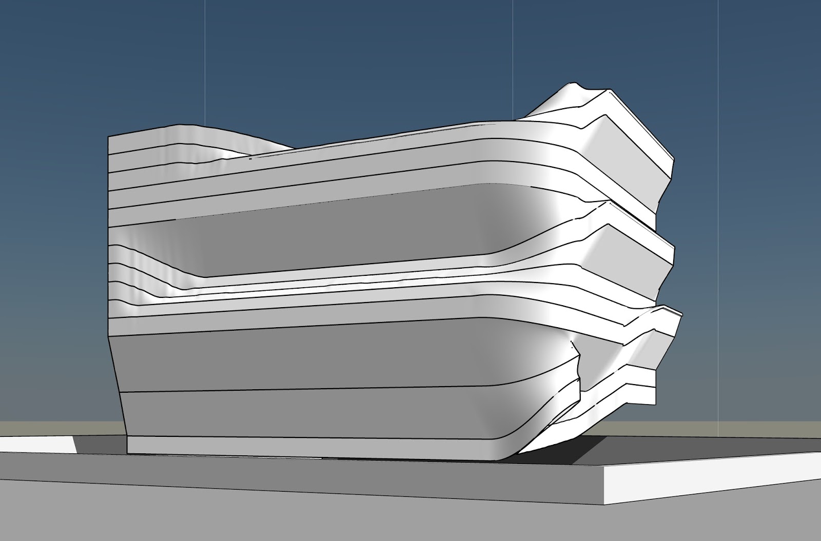
Then I decided to create two perpendicular surfaces (similar to the corner of a building) and then generate and manipulate the form with the images. The resulting mass is achieved by altering the image graphics and values to control the level of distortion.
The conceptual mass from which the below rough building model was created was not manipulated manually (except for a void cut out at the bottom right corner of the mass)

Outlined below are the various steps that led to creating this.
The dynamo file below creates a series of curves by connecting the reference points (whose positions are determined by the graphics in the images)
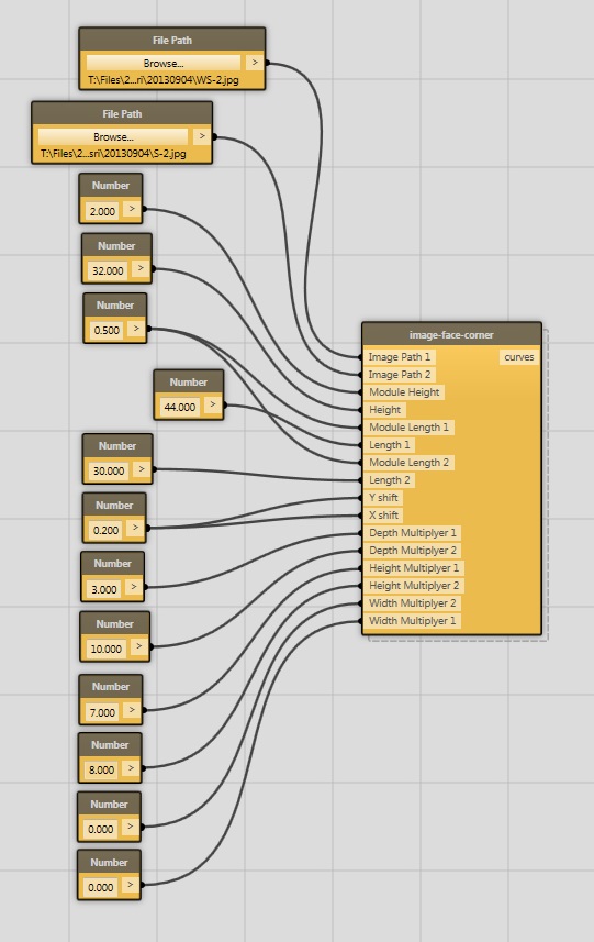
The slightly untidy image-face-corner node that creates a list of curves

The images visible above are the ones that drive the points and geometry of the curves that are generated.

The intention was to generate a loft form from these curves. But this did not always work as expected.
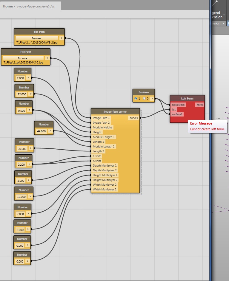
The work around was to create a loft form with a pair of curves at a time. A new node Sequential Loft was created to achieve this by drawing inspiration from the Connect Points node.


The sequential Loft node
This can now be taken to Revit and worked upon.